Generic Reference Driver
Synopsis
Address: 127.127.8.u
Reference ID: PARSE
Driver ID: GENERIC
Serial Port: /dev/refclock-u; TTY mode according to
clock type
Description
The timecode of these receivers is sampled via a STREAMS module in the
kernel (The STREAMS module has been designed for use with SUN Systems
under SunOS 4.1.x or Solaris 2.3 - 2.6. It can be linked directly into
the kernel or loaded via the loadable driver mechanism). This STREAMS
module can be adapted to be able to convert different time code formats.
If the daemon is compiled without the STREAM definition synchronization
will work without the Sun streams module, though accuracy is
significantly degraded. This feature allows to use PARSE also on non Sun
machines.
The actual receiver status is mapped into various synchronization
states generally used by receivers. The STREAMS module is configured to
interpret the time codes of DCF C51, PZF535, PZF509, GPS166, Trimble SV6
GPS, ELV DCF7000, Schmid and low cost receivers (see list below).
The reference clock support in ntp contains the necessary
configuration tables for those receivers. In addition to supporting
several different clock types and 4 devices, the generation a a PPS
signal is also provided as an configuration option. The PPS
configuration option uses the receiver generated time stamps for feeding
the PPS loopfilter control for much finer clock synchronization.
CAUTION: The PPS configuration option is different from the hardware
PPS signal, which is also supported (see below), as it controls the way
ntpd is synchronized to the reference clock, while the hardware PPS
signal controls the way time offsets are determined.
The use of the PPS option requires receivers with an accuracy of
better than 1ms.
Fudge factors
Only two fudge factors are utilized. The time1 fudge factor defines
the phase offset of the synchronization character to the actual time. On
the availability of PPS information the time2 fudge factor defines the
skew between the PPS time stamp and the receiver timestamp of the PPS
signal. This parameter is usually zero, as usually the PPS signal is
believed in time and OS delays should be corrected in the machine
specific section of the kernel driver. time2 needs only be set when the
actual PPS signal is delayed for some reason. The flag1 enables input
filtering. This a median filter with continuous sampling. The flag2
selects averaging of the samples remaining after the filtering. Leap
second-handling is controlled with the flag3. When set a leap second
will be deleted on receipt of a leap second indication from the
receiver. Otherwise the leap second will be added, (which is the
default). flag3 should never be set. PPS handling is enabled by adding
128 to the mode parameter in the server/peer command.
ntpq (8)
timecode variable
The ntpq program can read clock variables command list several
variables.
These hold the following information: refclock_time is the local time
with
the offset to UTC (format HHMM). The currently active receiver flags are
listed in refclock_status. Additional feature flags of the receiver are
optionally listed in parentheses. The actual time code is listed in
timecode.
A qualification of the decoded time code format is following in
refclock_format.
The last piece of information is the overall running time and the
accumulated
times for the clock event states in refclock_states. When PPS
information
is present additional variable are available. refclock_ppstime lists
then
the PPS timestamp and refclock_ppsskew lists the difference between
RS232
derived timestamp and the PPS timestamp.
Currently, fourteen clock types (devices /dev/refclock-0 -
/dev/refclock-3)
are supported by the PARSE driver.
A note on the implementations:
The pictures below refer to the respective clock and where taken from
the
vendors web pages. They are linked to the respective vendors.
-
server 127.127.8.0-3 mode 0
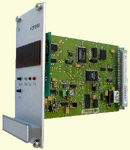
Meinberg PZF535/PZF509
receiver (FM demodulation/TCXO / 50us)
-
server 127.127.8.0-3 mode 1
Meinberg PZF535/PZF509
receiver (FM demodulation/OCXO / 50us)
-
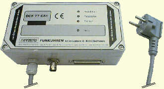
server 127.127.8.0-3 mode 2
Meinberg DCF U/A
31/DCF C51 receiver
(AM demodulation / 4ms)
-
server 127.127.8.0-3 mode 3
ELV DCF7000 (sloppy AM
demodulation
/ 50ms)
-
server 127.127.8.0-3 mode 4
Walter Schmid DCF receiver Kit (AM demodulation /
1ms)
-
server 127.127.8.0-3 mode 5
RAW DCF77 100/200ms pulses (Conrad DCF77 receiver module /
5ms)
-
server 127.127.8.0-3 mode 6
RAW DCF77 100/200ms pulses (TimeBrick DCF77 receiver module
/ 5ms)
-
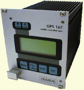
server 127.127.8.0-3 mode 7
Meinberg GPS166/GPS167
receiver (GPS / <<1us)
-
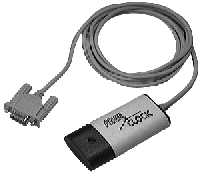
server 127.127.8.0-3 mode 8
IGEL clock
-
server 127.127.8.0-3 mode 9
Trimble SVeeSix
GPS receiverTAIP protocol (GPS / <<1us)
-
server 127.127.8.0-3 mode 10
Trimble SVeeSix
GPS receiver TSIP protocol (GPS / <<1us) (no kernel support
yet)


-
server 127.127.8.0-3 mode 11
Radiocode Clocks Ltd RCC 8000 Intelligent Off-Air Master
Clock
support
-
server 127.127.8.0-3 mode 12
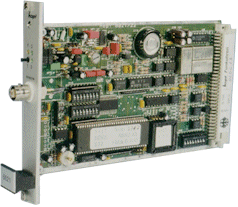
HOPF Funkuhr
6021
-
server 127.127.8.0-3 mode 13
Diem's Computime Radio Clock
-
server 127.127.8.0-3 mode 14
RAWDCF receiver (DTR=high/RTS=low)
Actual data formats and set-up requirements of the various clocks can be
found in NTP PARSE clock data formats.
The reference clock support carefully monitors the state transitions
of the receiver. All state changes and exceptional events such as loss
of time code transmission are logged via the syslog facility. Every hour
a summary of the accumulated times for the clock states is listed via
syslog.
PPS support is only available when the receiver is completely
synchronized.
The receiver is believed to deliver correct time for an additional
period
of time after losing synchronizations, unless a disruption in time code
transmission is detected (possible power loss). The trust period is
dependent
on the receiver oscillator and thus a function of clock type. This is
one
of the parameters in the clockinfo field of the reference clock
implementation.
This parameter cannot be configured by ntpdc.
In addition to the PPS loopfilter control a true PPS hardware signal
can be applied on Sun Sparc stations via the CPU serial ports on the CD
pin. This signal is automatically detected and will be used for offset
calculation. The input signal must be the time mark for the following
time
code. (The edge sensitivity can be selected - look into the appropriate
kernel/parsestreams.c for details). Meinberg receivers can be connected
by feeding the PPS pulse of the receiver via a 1488 level converter to
Pin 8 (CD) of a Sun serial zs-port. To select PPS support the STREAMS
driver
for PARSE must be loaded and the mode parameter ist the mode value of
above
plus 128. If 128 is not added to the mode value PPS will be detected to
be available but it will not be used. For PPS to be used you MUST add
128
to the mode parameter.
For the Meinberg GPS166/GPS167 receiver is also a special firmware
release
available (Uni-Erlangen). This release should be used for proper
operation.
The raw DCF77 pulses can be fed via a level converter directly into
Pin 3 (Rx) of the Sun. The telegrams will be decoded an used for
synchronization.
AM DCF77 receivers are running as low as $25. The accuracy is dependent
on the receiver and is somewhere between 2ms (expensive) to 10ms
(cheap).
Upon bad signal reception of DCF77 synchronizations will cease as no
backup
oscillator is available as usually found in other reference clock
receivers.
So it is important to have a good place for the DCF77 antenna. For
transmitter
shutdowns you are out of luck unless you have other NTP servers with
alternate
time sources available.
Monitor Data
clock states statistics are written hourly the the syslog service.
Online
information can be found by examining the clock variable via the ntpq cv
command.
Fudge Factors
-
time1 time
-
Specifies the time offset calibration factor, in seconds and fraction,
with default depending on clock type.
-
time2 time
-
Specifies the offset if the PPS signal to the actual time. (PPS fine
tuning).
-
stratum number
-
Specifies the driver stratum, in decimal from 0 to 15, with default
0.
-
refid string
-
Specifies the driver reference identifier, an ASCII string from one to
four characters, with default according to current clock type.
-
flag1 0 | 1
-
Not used by this driver.
-
flag2 0 | 1
-
Not used by this driver.
-
flag3 0 | 1
-
delete next leap second instead of adding it.
-
flag4 0 | 1
-
Delete next leap second instead of adding it - flag will be re-defined
soon - so don't use it. Statistics are provided by more common means
(syslog,
clock variable via ntpq)
Making your own PARSE clocks
The pare clock mechanismis deviated from the way other ntp reference
clocks
work. For a short description how to build parse reference clocks see making
PARSE clocks
Additional Information
Reference Clock Drivers
 David L. Mills <[email protected]>


 David L. Mills <